1 University of Michigan Transportation Research Institute
2 University of Michigan Department of Biomedical Engineering
Ann Arbor, MI 48105
ABSTRACT
Achieving proper fit of the shoulder-belt for the wide range of students who remain in their wheelchairs during transport in school buses requires adjustability of the location of the upper shoulder-belt anchor point. In this study, optimal upper shoulder-belt anchor point locations from 342 wheelchair frontal-impact sled tests conducted in accordance with ANSI/RESNA WC19 were used to determine the fore-aft adjustment ranges needed to achieve proper shoulder-belt fit in two bus configurations. The range of preferred locations for the upper shoulder-belt anchor point runs from approximately 737 mm (29 in) behind the rear wheelchair tiedown anchor points to 508 mm (20 in) forward of the rear tiedown anchor point, depending on the height of the bus windows where these anchor points are typically installed.
KEYWORDS
wheelchair transportation safety, school bus, wheelchair-seated students, shoulder-belt anchor points
BACKGROUND
Many students with special healthcare needs remain in their wheelchairs during transport on school buses. Good fit of a crashworthy lap/shoulder belt system (i.e., a three-point occupant restraint) is necessary to enhance occupant protection in the event of a crash, emergency braking, and high-speed turns. Ideally, the belt-restraint system will apply occupant restraint forces to strongest parts of the skeleton (i.e. the pelvis, the middle of the outboard shoulder, and the sternum). Studies have shown that good fit of the lap/shoulder belt is often difficult to achieve on wheelchair-seated travelers due to interference of wheelchair components with proper belt placement, and also that nonuse/misuse of belt restraints is common (1, 2). Much of the misuse and nonuse of crashworthy belt restraints for wheelchair-seated travelers is due to a lack of knowledge of best-practice procedures. However, the location of belt-restraint anchorage hardware within the vehicle can also have a significant effect on the proper fit of lap/shoulder belts, especially in school and public transit situations where the same station must accommodate many wheelchair users.
Federal Motor Vehicle Safety Standard (FMVSS) 222 School Bus Passenger Seating and Crash Protection provides occupant protection requirements for school bus passengers, including requirements for equipment installed by bus manufacturers to secure occupied wheelchairs and to provide protection for students who remain seated in their wheelchairs (3). Although FMVSS 222 specifies the number and strength of wheelchair securement and occupant-restraint anchor points, it does not specify any location requirements.
The Society of Automotive Engineers (SAE) J2249 Wheelchair Tiedowns and Occupant Restraint Systems, which is being upgraded and will soon become Section 18, Wheelchair Tiedown and Occupant Restraint Systems for Use in Motor Vehicles of RESNA Wheelchair Standards Volume 4 establishes design and performance standards for wheelchair tiedown and occupant restraint systems (4, 5). While J2249 specifies requirements for the length adjustments of lap and shoulder-belts to accommodate a wide range of wheelchair users and Annex F provides informative guidelines on zones for preferred locations of shoulder-belt upper anchor points relative to the wheelchair occupant’s shoulder, it does not define these zones for a wide range of wheelchair users or express them relative to landmarks in the wheelchair station.
National guidelines for pupil transportation are established by the National Congress on School Transportation (NCST) and are adopted by a subset of states/districts in full but are more often used as “best-practice guidelines” nationwide. The 2005 NCST edition provides guidelines for routing the lap belt and states that a “height adjuster” may be required to achieve proper belt positioning, but it does not interpret the guidelines relative to the bus environment and does not specify a range of anchor point locations needed to achieve preferred belt positioning on a range of wheelchair-seated students.
OBJECTIVE
This study used optimal upper shoulder-belt anchor point location data from 342 frontal-impact tests to define fore-aft locations and adjustment ranges for shoulder-belt upper anchor points in school buses relative to rear tiedown strap anchor points.
METHODS
Overview
When conducting a frontal-impact test in accordance with the voluntary standard ANSI/RESNA WC19, Wheelchairs Used as Seats in Motor Vehicles, the fixed upper shoulder-belt anchor point is located to achieve optimal upper torso restraint (6, 7). This is accomplished by creating a side-view angle of the shoulder-belt as it comes off the dummy’s shoulder of 30° ± 5°. The rear tiedown geometry is also optimized by setting the side-view angle of the straps to 45° ± 3°. Because the locations of the upper shoulder-belt anchor points relative to these standardized rear tiedown anchor points were not directly measured at the initial time of sled testing, quantitative analysis of pre-test photos for a range of wheelchair types and crash-dummy sizes was performed. The resulting data provides a means for estimating the fore-aft range of upper shoulder-belt anchor points needed to accommodate the proper placement and fit of shoulder-belts on the range of wheelchair-seated students in school buses.
Photo Analysis
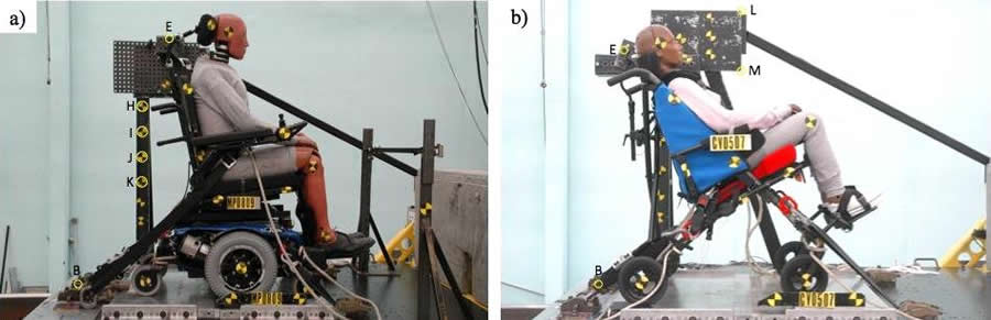 Figure 1. Pre-test side-view photos and digitized points from WC19 setups for a power wheelchair (a) and a stroller wheelchair (b).
Selected points on pre-test side-view set-up photos from WC19 wheelchair tests conducted at the University of Michigan Transportation Research Institute (UMTRI) from 2002 through 2009 were digitized using ImageJ, a Java-based image-processing program. As indicated in Figure 1, fixed points on the sled stanchion representing the sidewall of the vehicle were measured and used to scale points digitized in the photos to determine their physical locations in the test setup. All digitized points, including the upper shoulder-belt anchor point and the sled stanchion targets, were located in the same longitudinal side-view plane and were measured with respect to the aluminum platform that represents the ground plane or vehicle floor and the vertical line (HK) through the rear post of the sled stanchion. As shown in Figures 1a and 1b, depending on the visibility of the points in the side-view photos, different points were used as references (e.g. H, I, or M) to interpret the locations of the upper shoulder-belt anchor points with respect to the ground plane and the rear tiedown anchor points.
Window-Top Heights for School Buses
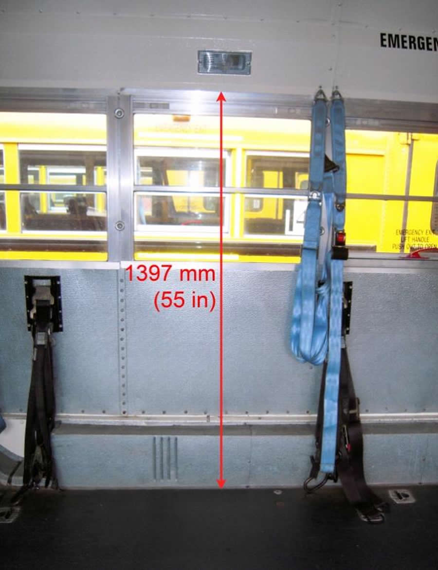 Figure 2. Photo of interior side wall of a 2001 model year school bus showing the height from floor to top of windows measured at 1397 mm (55 in) and belt restraint for wheelchair-seated students hanging from upper anchor points above the windows.
Since the goal of the study was to determine the range for upper shoulder-belt anchor points that will allow for adjusting the upper shoulder-belt anchor point to achieve a good belt fit to a wide range of students, it was assumed that in some cases the anchor points would need to be located above the top of the bus windows. For the purposes of this study, the interiors of two school buses were inspected and the heights of the window tops measured. These buses were a 2001 wheelchair-accessible International school bus and a 2010 International school bus. Figure 2 shows the interior of one of the wheelchair-accessible school buses.
RESULTS
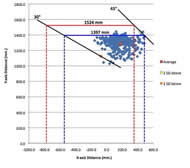 Figure 3. Upper shoulder-belt anchor points relative to rear tiedown anchor points from analysis of 342 pre-test WC19 setup side-view photos. The intersections of 30° and 45° lines drawn through the lower/rearward and upper/forward ± 2 standard deviation points from the overall mean upper anchor point, respectively, with the horizontal lines corresponding to the top-of-window heights of two school buses are shown.
Side-view pre-test photos from a total of 342 wheelchair sled tests were digitized, including tests of 81 stroller wheelchairs, 89 manual wheelchairs, and 138 power wheelchairs. The crash-test dummies used in these tests included 229 that represent midsize adult males, 31 that represent large adult males, 39 that represent small adult females, eleven that represent 10-year-old children, and five that represent 6-year-old children. Figure 3 shows a two-dimensional side-view plot of all of the upper shoulder-belt anchor points relative to the rear tiedown anchor points, which is indicated by coordinates 0.0 and 0.0 on the X and Y axes. The distances from the floor to the top of the windows in the 2001 and 2010 school buses are 1397 millimeters (55 in) and 1524 millimeters (60 in), respectively.
The average horizontal distance of the upper shoulder-belt anchor point forward of the rear tiedown anchor point is 177.6 mm with a standard deviation of ±126.2 millimeters (7.0 in ± 5.0 in). The location of the upper shoulder-belt anchor point ranges from 155.4 mm (6.1 in) behind the rear tiedown anchor point to 488.5 mm (19.2 in) forward of the rear tiedown anchor point. The average height of the upper shoulder-belt anchor point above the ground plane is 1284.8 mm with a standard deviation of 80.0 mm (50.6 in ± 3.2 in). The height of the upper shoulder-belt anchor point above the ground plane ranges from 1027.8 mm (40.5 in) to 1443.6 mm (56.8 in).
In Figure 3, points corresponding to ± two standard deviations in the fore/aft and up/down directions from the average upper shoulder-belt anchor point locations are indicated by the orange and yellow circle symbols. Using these points, lines were drawn at 30° and 45° to the horizontal since these angles represent the range of preferred side-view shoulder-belt angles from the top of the occupant’s shoulder to the upper anchor point. The intersections of these lines with the horizontal lines corresponding to the top-of-window heights for the two school buses gives the range of upper anchor point locations needed to achieve good shoulder-belt fit on the range of potential student passengers seated in wheelchairs. In particular, the intersection of the 30° line drawn from the lower and rearward (two standard deviations below) point with the top-of-window line and the intersection of the 45° line drawn from the forward and upward (two standard deviations above) point indicate the ideal adjustment range for the upper shoulder-belt anchor point relative to the rear tiedown anchor point. These ranges are illustrated by the solid blue and red lines for the two top-of-window heights measured in the 2001 and 2010 school buses, respectively. As indicated, the range of preferred locations for the upper shoulder-belt anchor in the 2010 International bus runs from approximately 775 mm (30.5 in) behind the rear wheelchair tiedown anchor points to 355 mm (14.0 in) forward of the rear tiedown anchor points. For the 2001 school bus, the preferred range of upper shoulder-belt anchor point locations runs from approximately 546 mm (21.5 in) behind the rear tiedown anchor point to 488 mm (19.2 in) forward of the rear tiedown anchor point.
DISCUSSION
The process used to measure the upper shoulder-belt anchor point locations has potential errors due to manually digitizing points in the pre-test side-view photos. However, to minimize errors in converting digitized points to physical distances, all digitized points were in the same longitudinal plane relative to the side-view camera. Although the set of sled tests used in this study includes a diverse sample of wheelchair types and sizes as well as crash-dummy sizes, it is unlikely that the distributions of these variables are representative of wheelchairs and students in the school bus population. Locations and ranges of upper shoulder-belt anchor points were determined for only two vehicle interiors (i.e. top-of-window heights). However, these anchor point location data can be used to estimate the preferred anchor point locations and adjustment ranges for other school bus interiors by determining the intersections of the top-of-window height lines with the 30° and 45° shoulder-belt lines drawn from the ± two standard deviations points.
CONCLUSIONS
Fore-aft locations and adjustment ranges for shoulder-belt upper anchor points were determined for two school bus interiors relative to wheelchair rear tiedown strap anchor points using optimal anchor point data from WC19 sled-test setups. The range of preferred locations for upper shoulder-belt anchor points in the 2010 International bus runs from approximately 737 mm (29 in) behind the rear wheelchair tiedown anchor points to 330 mm (13 in) forward of the rear tiedown anchor points. For the 2001 school bus, the preferred range of upper shoulder-belt anchor-point locations runs from approximately 533 mm (21 in) behind the rear tiedown anchor point to 508 mm (20 in) forward of the rear tiedown anchor point. This information will benefit school bus manufacturers, bus modifiers, and transportation providers by providing guidelines for where to locate upper shoulder-belt anchor points to accommodate various wheelchair-seated occupants.
REFERENCES
- Klinich, KD, Moore, JL, Manary, MA, and Schneider, LW. (2006). Use and Performance of Occupant Restraint Systems for Wheelchair Users in Real-World Crashes. RESNA Annual Conference Proceedings, Atlanta, GA.
- Schneider, LW, Klinich, KD, Moore, JL, and MacWilliams, JB. (in press). Using In-Depth Investigations to Identify Safety Issues for Wheelchair-Seated Occupants of Motor Vehicles. Medical Engineering and Physics.
- Code of Federal Regulations, Title 49, Transportation, Part 571.222, School bus seating and crashworthiness, Washington, DC, 1998, National Archives and Records Service, Office of the Federal Register.
- Society of Automotive Engineers (SAE). (1999). Recommended Practice J2249 Wheelchair Tiedown and Occupant Restraint Systems for Use in Motor Vehicles. In 2002 SAE Handbook, pp. 229-244, Society of Automotive Engineers, Warrendale, PA.
- American National Standards Institute/Rehabilitation Engineering and Assistive Technology Society of North America (ANSI/RESNA). (2009). Section 18 ANSI/RESNA WC/Volume 4: Wheelchairs and Transportation - Wheelchair Tiedown and Occupant Restraint Systems for Use in Motor Vehicles, Arlington, VA.
- American National Standards Institute/Rehabilitation Engineering and Assistive Technology Society of North America (ANSI/RESNA). (2000). Section 19 ANSI/RESNA WC/Volume 1:Wheelchairs -Wheelchairs Used as Seats in Motor Vehicles, Arlington, VA.
- Schneider, LW, Manary, MA, Hobson, DA, and Bertocci, GE. (2009). Transportation Safety Standards for Wheelchair Users: A Review of Voluntary Standards for Improved Safety, Usability, and Independence of Wheelchair-Seated Travelers, Assistive Technology Volume 20.4, Winter/2008 RESNA Press, Arlington, VA.
ACKNOWLEDGEMENTS
This research was supported by the National Institute on Disability and Rehabilitation Research (NIDRR) through funding of the Rehabilitation Engineering and Research Center on Wheelchair Transportation Safety (RERC WTS) under grant number H133E060064. The opinions expressed herein are those of the authors and are not necessarily reflective of the opinions of the NIDRR.
Author Contact Information:
Katie Ewing, BSE, University of Michigan, 1225 Island Dr. #203, Ann Arbor, MI 48105, Home Phone (734) 332-3373, E-MAIL: kaewing@umich.edu Word Version PDF Version